Position:Home » Technical Articles
Resistors in Light Emitting Diode (LED) Circuits
Writer:Microhm Page View:Date:2019-06-19
An LED (Light Emitting Diode) emits light when an electric current passes through it. The simplest circuit to power an LED is a voltage source with a resistor and an LED in series. Such a resistor is often called a ballast resistor. The ballast resistor is used to limit the current through the LED and to prevent that it burns. If the voltage source is equal to the voltage drop of the LED, no resistor is required. The resistance of the ballast resistor is easy to calculate with Ohm’s law and Kirchhoff’s circuit laws.
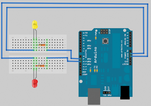
All LEDs require some form of current limiting. Connecting an LED directly to the power supply will burn it out immediately. Overdriving, even briefly, will significantly reduce it's life and light output.
Fortunately, driving a single or a string of low current (20-30 mA) LEDs is a simple task - adding a small resistor in series is the easiest and cheapest way to limit the current.
Keep in mind however, that high current (above a few hundreds of mA) LEDs are tougher to drive, and while they can be operated with a series resistor, to minimize power loss and ensure reliability, it's advisable to use a more expensive switching current regulator.
We should avoid connecting LEDs in parallel with just one resistor shared between them. Identical LEDs can be successfully connected in parallel, but each LED may have a slightly different voltage drop, and the brightness of the LEDs will differ. If you want to connect the LEDs in parallel each one should have its own resistor. Calculate the value for a single LED and connect all the LED-resistor pairs in parallel.
Keywords:
Latest News
- Resistor's role in measuring and correcting LED,,,
- Single through-hole resistors' characteristics ,,,
- Why shunt resistors for current sense applicati,,,
- Metal-film resistors with small size, high resi,,,
- 36W High-Current Shunt Resistors MMS8420,,,
- 1W Surface Mount Resistor MPR1206,,,
- An Overview of Microhm Electronics' Resistor Pr,,,
- More anti-sulfur resistors used in harsh envir,,,
- Resistance changes with temperature,,,
- 140W TO247 High Power Heatsinkable Resistor,,,
- MMS5930 is ideal for current sensing in industr,,,
- Shunt resistors selection for engineers' design,,,
- Considerations for choosing precision resistors,,,
- Ceramic Encased Cement Resistors NWH Series for,,,
- Resistors for Passive Balancing in Battery-Pow,,,
Hot Articles
- Microhm will take part in 10th Automotive World,,,
- Thanks for Visiting Microhm's Booth E5-5706 in ,,,
- Resistors in Short Supply: Blame Cars,,,
- New lunch: High Power Precision Shunt Resistor,,,,
- How to Test a Resistor,,,
- Innovative Technology, Future Electric: Electri,,,
- What is Precision Resistors?,,,
- SMD Resistors Sizes and Packages,,,
- The Construction and Features of Metal Film Res,,,
- What is a TO-220 Resisor?,,,
- Hot Selling Products: Precision Shunt Resistors,,,
- How to Calculate the Equivalent Resistance Valu,,,
- What is a Fixed Resistor?,,,
- Resistors in LED Circuits,,,
- Resistors Types and Materials Overview,,,
Resistance applications
- The Main Application for High Precision and Low,,,
- Miniature future for passive electronic compone,,,
- Difference Between High Precision Resistors and,,,
- Shunt Resistor MMS8420 for High Current Stable ,,,
- Urbanization Development Bringing the Transform,,,
- Industrial Roberts Applied to Solar Photovoltai,,,
- Precision Resistors' Construction and TCR,,,
- Heater Blower Motor Resistor in Air Conditioner,,,
- The Four Important Functions of Alloy Resistors,,,
- Carbon Film Resistors' Features and Application,,,
- Why Zero-Ohm Resistors?,,,
- Surface Mount Resistor's Size and Package ,,,
- BMS for New Energy Vehicle,,,
- The Measurement Accuracy of Automotive Shunt is,,,
- Select the Right Resistor for Harmonic Filterin,,,