Position:Home » Technical Articles
Thick Film Technology
Writer:Microhm Page View:Date:2019-05-27
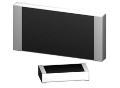
Thick film chip resistor started to gain popularity in the 1970s. Today, these are by far the most used resistors in electrical and electronic devices. They come usually as chip resistor (SMD), and have the lowest cost compared to any other technology.
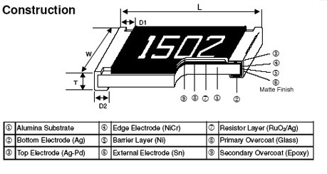
The resistive material is a special paste with a mixture of a binder, a carrier, and the metal oxides to be deposited. The binder is a glassy frit and the carrier exists of organic solvent systems and plasticizers. Modern resistor pastes are based on oxides of ruthenium, iridium and rhenium. This is also referred to as a cermet (Ceramic – Metallic). The resistive layer is printed onto a substrate at 850°C. The substrate is often 95% alumina ceramic. After the firing of the paste on the carrier, the film becomes glasslike, which makes it well protected against moisture. The thickness is in the order of 100 micrometer. This is approximately 1000 times more than thin film. Unlike thin film, this process is additive. This means that the resistive layers are added sequentially to the substrate to create the conducting patterns and resistance values.
The temperature coefficient of thick film resistors typically ranges from 50 ppm to 200 ppm/K. Tolerances are between 1% and 5%. Because costs are low, thick film is generally preferred in case no high tolerances, low TCR or high stability is required. Therefore, these resistors can be found in almost any device with an AC plug or a battery. Advantages of thick over thin technology are not only lower cost, but also the ability to handle more power, provide a wider range of resistance values and withstand high surge conditions.
Keywords:
Latest News
- Resistor's role in measuring and correcting LED,,,
- Single through-hole resistors' characteristics ,,,
- Why shunt resistors for current sense applicati,,,
- Metal-film resistors with small size, high resi,,,
- 36W High-Current Shunt Resistors MMS8420,,,
- 1W Surface Mount Resistor MPR1206,,,
- An Overview of Microhm Electronics' Resistor Pr,,,
- More anti-sulfur resistors used in harsh envir,,,
- Resistance changes with temperature,,,
- 140W TO247 High Power Heatsinkable Resistor,,,
- MMS5930 is ideal for current sensing in industr,,,
- Shunt resistors selection for engineers' design,,,
- Considerations for choosing precision resistors,,,
- Ceramic Encased Cement Resistors NWH Series for,,,
- Resistors for Passive Balancing in Battery-Pow,,,
Hot Articles
- Microhm will take part in 10th Automotive World,,,
- Thanks for Visiting Microhm's Booth E5-5706 in ,,,
- Resistors in Short Supply: Blame Cars,,,
- New lunch: High Power Precision Shunt Resistor,,,,
- How to Test a Resistor,,,
- Innovative Technology, Future Electric: Electri,,,
- What is Precision Resistors?,,,
- SMD Resistors Sizes and Packages,,,
- The Construction and Features of Metal Film Res,,,
- What is a TO-220 Resisor?,,,
- Hot Selling Products: Precision Shunt Resistors,,,
- How to Calculate the Equivalent Resistance Valu,,,
- What is a Fixed Resistor?,,,
- Resistors in LED Circuits,,,
- Resistors Types and Materials Overview,,,
Resistance applications
- Shunt Resistor MMS8420 for High Current Stable ,,,
- Miniature future for passive electronic compone,,,
- Why Zero-Ohm Resistors?,,,
- Industrial Roberts Applied to Solar Photovoltai,,,
- The Four Important Functions of Alloy Resistors,,,
- The Measurement Accuracy of Automotive Shunt is,,,
- Select the Right Resistor for Harmonic Filterin,,,
- The Main Application for High Precision and Low,,,
- Difference Between High Precision Resistors and,,,
- BMS for New Energy Vehicle,,,
- Urbanization Development Bringing the Transform,,,
- Precision Resistors' Construction and TCR,,,
- Heater Blower Motor Resistor in Air Conditioner,,,
- Carbon Film Resistors' Features and Application,,,
- Surface Mount Resistor's Size and Package ,,,