The Standard Resistor Colour Code Chart and Value Calculation
Writer:Microhm Page View:Date:2019-06-20
An international and universally accepted resistor colour code scheme was developed many years ago as a simple and quick way of identifying a resistors ohmic value no matter what its size or condition. It consists of a set of individual coloured rings or bands in spectral order representing each digit of the resistors value.
The resistor colour code markings are always read one band at a time starting from the left to the right, with the larger width tolerance band oriented to the right side indicating its tolerance. By matching the colour of the first band with its associated number in the digit column of the colour chart below the first digit is identified and this represents the first digit of the resistance value.
Again, by matching the colour of the second band with its associated number in the digit column of the colour chart we get the second digit of the resistance value and so on. Then the resistor colour code is read from left to right as illustrated below:
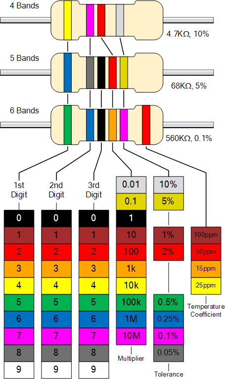
Resistor Color Code Chart
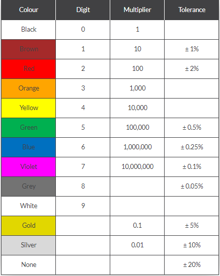
Resistor Color Code Table
The Resistor Colour Code system is all well and good, but we need to understand how to apply it in order to get the correct value of the resistor. The “left-hand” or the most significant coloured band is the band which is nearest to a connecting lead with the colour coded bands being read from left-to-right .
Most five band resistors are precision resistors with tolerances of either 1% or 2% while most of the four band resistors have tolerances of 5%, 10% and 20%. If resistor has no fourth tolerance band then the default tolerance would be at 20%.
Keywords:Resistor Col
Latest News
- Resistor's role in measuring and correcting LED,,,
- Single through-hole resistors' characteristics ,,,
- Why shunt resistors for current sense applicati,,,
- Metal-film resistors with small size, high resi,,,
- 36W High-Current Shunt Resistors MMS8420,,,
- 1W Surface Mount Resistor MPR1206,,,
- An Overview of Microhm Electronics' Resistor Pr,,,
- More anti-sulfur resistors used in harsh envir,,,
- Resistance changes with temperature,,,
- 140W TO247 High Power Heatsinkable Resistor,,,
- MMS5930 is ideal for current sensing in industr,,,
- Shunt resistors selection for engineers' design,,,
- Considerations for choosing precision resistors,,,
- Ceramic Encased Cement Resistors NWH Series for,,,
- Resistors for Passive Balancing in Battery-Pow,,,
Hot Articles
- Microhm will take part in 10th Automotive World,,,
- Thanks for Visiting Microhm's Booth E5-5706 in ,,,
- Resistors in Short Supply: Blame Cars,,,
- New lunch: High Power Precision Shunt Resistor,,,,
- How to Test a Resistor,,,
- Innovative Technology, Future Electric: Electri,,,
- What is Precision Resistors?,,,
- SMD Resistors Sizes and Packages,,,
- The Construction and Features of Metal Film Res,,,
- What is a TO-220 Resisor?,,,
- Hot Selling Products: Precision Shunt Resistors,,,
- How to Calculate the Equivalent Resistance Valu,,,
- What is a Fixed Resistor?,,,
- Resistors in LED Circuits,,,
- Resistors Types and Materials Overview,,,
Resistance applications
- Precision Resistors' Construction and TCR,,,
- Miniature future for passive electronic compone,,,
- The Main Application for High Precision and Low,,,
- Select the Right Resistor for Harmonic Filterin,,,
- BMS for New Energy Vehicle,,,
- Difference Between High Precision Resistors and,,,
- Industrial Roberts Applied to Solar Photovoltai,,,
- Urbanization Development Bringing the Transform,,,
- The Measurement Accuracy of Automotive Shunt is,,,
- Why Zero-Ohm Resistors?,,,
- The Four Important Functions of Alloy Resistors,,,
- Shunt Resistor MMS8420 for High Current Stable ,,,
- Surface Mount Resistor's Size and Package ,,,
- Heater Blower Motor Resistor in Air Conditioner,,,
- Carbon Film Resistors' Features and Application,,,